Chapters in this post
You may have read my last #buildingreport about the raw floorboards in my Omega 42: Today those went into the next production step. To cut down cost and keep weight low, we first had decided not to fit the expensive classic Nautic Floor material, which is very nice and certainly of a decent quality, but with some 50 Euros per square meter, I was looking for some alternatives.
One suggestion was to have the floorboards simply painted with a white topcoat and Kiwi Grip applied. This is an anti-skid paint that works just fine and is mostly utilized for the deck of boats. On the inside I´ve never seen this. By having a plain white floor, I feared, the boat would adopt a kind of sterile look. More so because of the fact that her furniture and bulkheads are already white. I don´t want to sail a dentist´s surgery …
EVA foam: (My) Best solution for interior deck surface material

Thinking back to my GEKKO, I couldn´t get the EVA foam out of my head. This material is an ethylene-vinyl-acetate, which is the chemical name for it. Essentially, there is high and low density EVA-foam of which the high density variant is mostly used in yachting for decking material. I have a kind of mixed experience with EVA, both bad (saving money and buying it cheaply from amazon didn´t work and good (finally having a professional company delivering the deck material). So I asked our Teak-specialist if he could help out. And he agreed.
So we met today for a couple of hours to prepare the raw floorboards, digitalize each of the boards and discuss the shape, design and color of my later floorboards. Since this is a very interesting procedure that surely will be repeated when Christian will produce the cockpit and deck for the Omega 42, I took a ride to his workshop. Why? Because I did had some questions about how such a “simple thing” like a floorboard is produced by a boat professional. And behold: This is awesome and so interesting that the raw content is so extensive that I will produce at least a 3-part series of articles. First one: Digitalizing the floorboards.
Why digitalizing the floorboards?
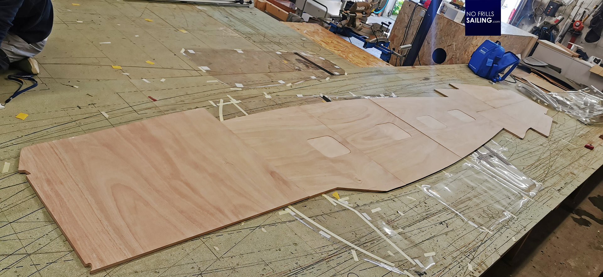
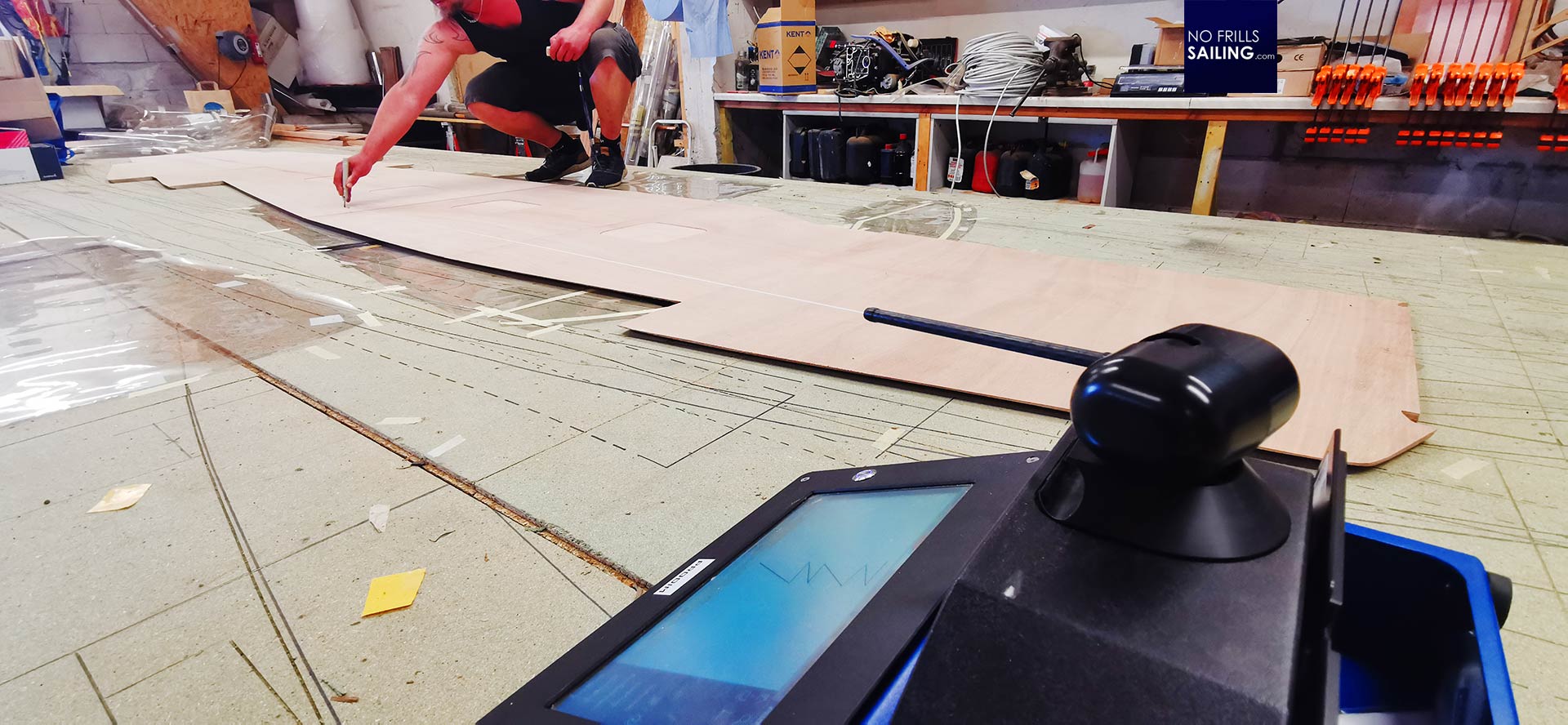
According to the pictures I took back in the shipyard we put together the floorboards on the large elevated working table in Christian´s workshop. This is the place where he assembles his nice woodworks and – with increasing numbers – the marine decks he is manufacturing. With the embargo of Myanmar Teak and the ongoing trend to become more and more sustainable, his income is generated by faux Teak and Teak-imitations. So, why digitalizing in the first place?
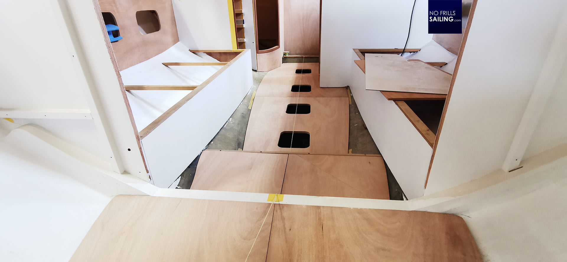
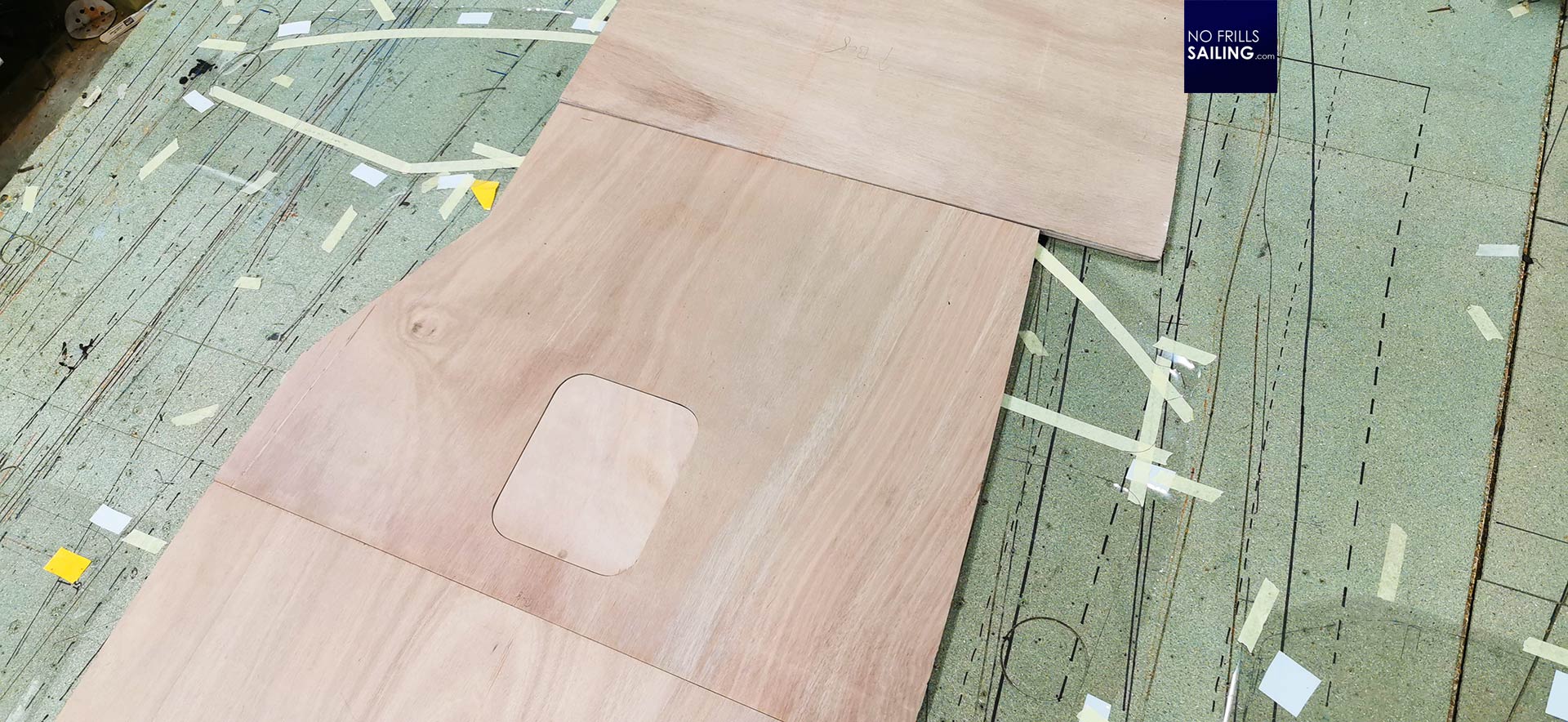
Well, looking at all of my Omega 42´s floorboards as a whole (and this picture due to the fisheye-effect cannot convey the true size) it becomes clear that you simply cannot just put on the EVA foam-parts. I already have tested this in my First 27 SE two years ago (read the article here) and it worked out just as fine, but on the First 27 it worked because each floorboard was a separate item put apart by large GRP stringers and the frame. Now, in the Omega 42 this is a new situation: All boards are together forming a single large unit – getting the interstices wrong from board to board would look like shit.

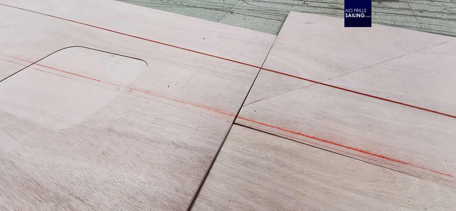
So we start by checking the centerline. Which, if you scroll back to the very first picture in this article, was futile since the craftsmen back in the shipyard – although working with a plumb-line – did not really manufacture the floorboards aligned to the centerline. Another reason for working with the plumb-line was to have the interstices align to the general “forward” of the boat. You remember my interior layout concept for this yacht: There are no doors except for the bathroom which means you can essentially look through all of the hull all the way down from stern to bow. Having the floorboard-interstices running along even half a degree offset would be noticeable and destroy the whole appearance of the yacht.
I find so much joy in such a relatively simple thing as a plumb-line. This is a red thread, coiled in a box which itself contains a marker. I guess some red-tinted chalk. By tightening the thread and having it flipping back down after some tensioning, the thread will leave a perfectly straight line of red chalk onto the underground, as you can see in the picture above. Except for the first two access-lids to the bilge and keel bolts, which are clearly out of centerline, I find we have found a perfect middle for the Omega 42 floor here.
The misalignment is of course not a produce of slatternliness or incompetence of the craftsmen in the shipyard but due to the fact that my boat is essentially a one-off. Each floorboard had been produced not by a CNC-machine that is working on a program that is adjusted to a millimeter, but by a skilled joiner who took measurements and had to adjust the form round by round whilst taking away material. Each time going in and out of the hull, applying new corrections, return to the boat and check the fit. Doing it this way some inaccuracies are absolutely normal and simply cannot be avoided. Nevertheless, a fortiori, it is paramount that every step in succession is done with utmost care and accuracy. That is why a very fascinating machine comes into play …
Digital templating for boat decks: Meet the Prodim Proliner
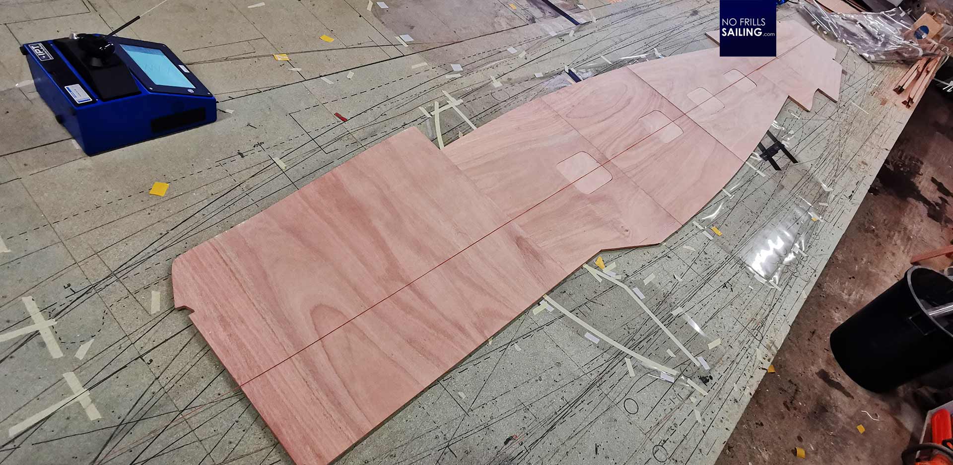
Christian unpacks and plugs in a blue machine. It looks like a mixture of one of those first generation home computers back in the Seventies with a control-unit of an industrial robot. And this picture isn´t all too much far-out from reality. The blue box is a “Ploliner” templating tool manufactured by the Dutch company Prodim Systems. Christian told me that the budget needed to buy such a tool was the single-most investment into his company last year – but having it was the key to the success.
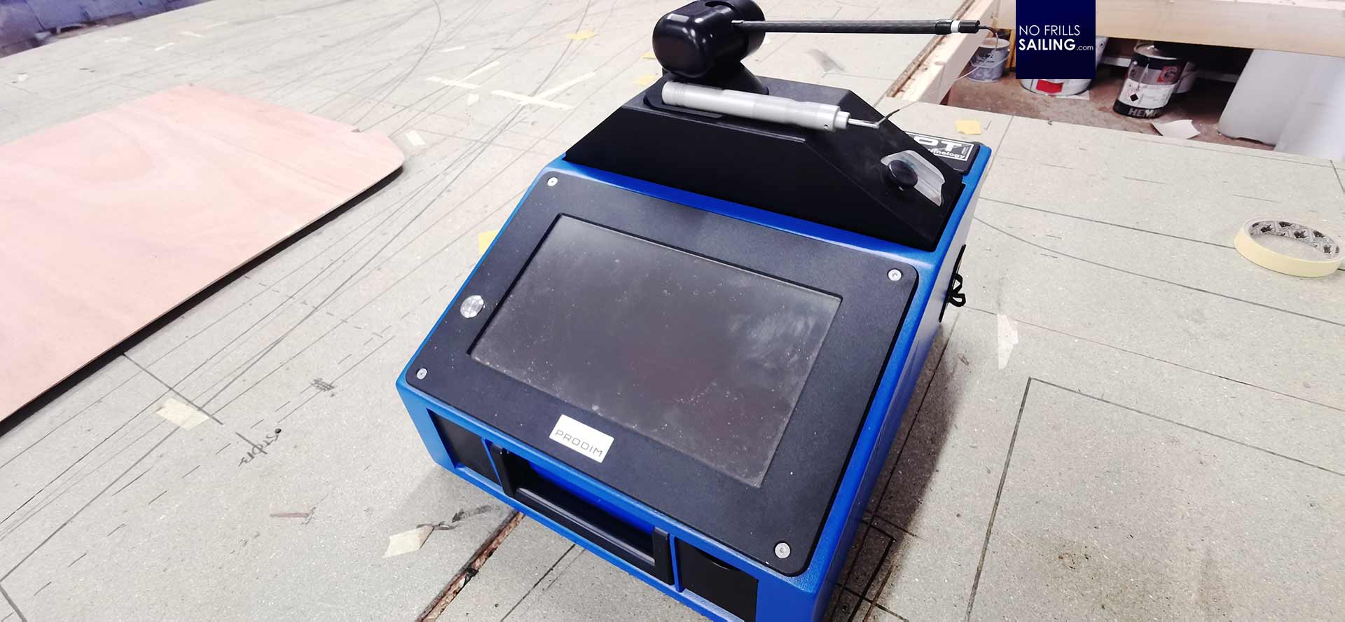
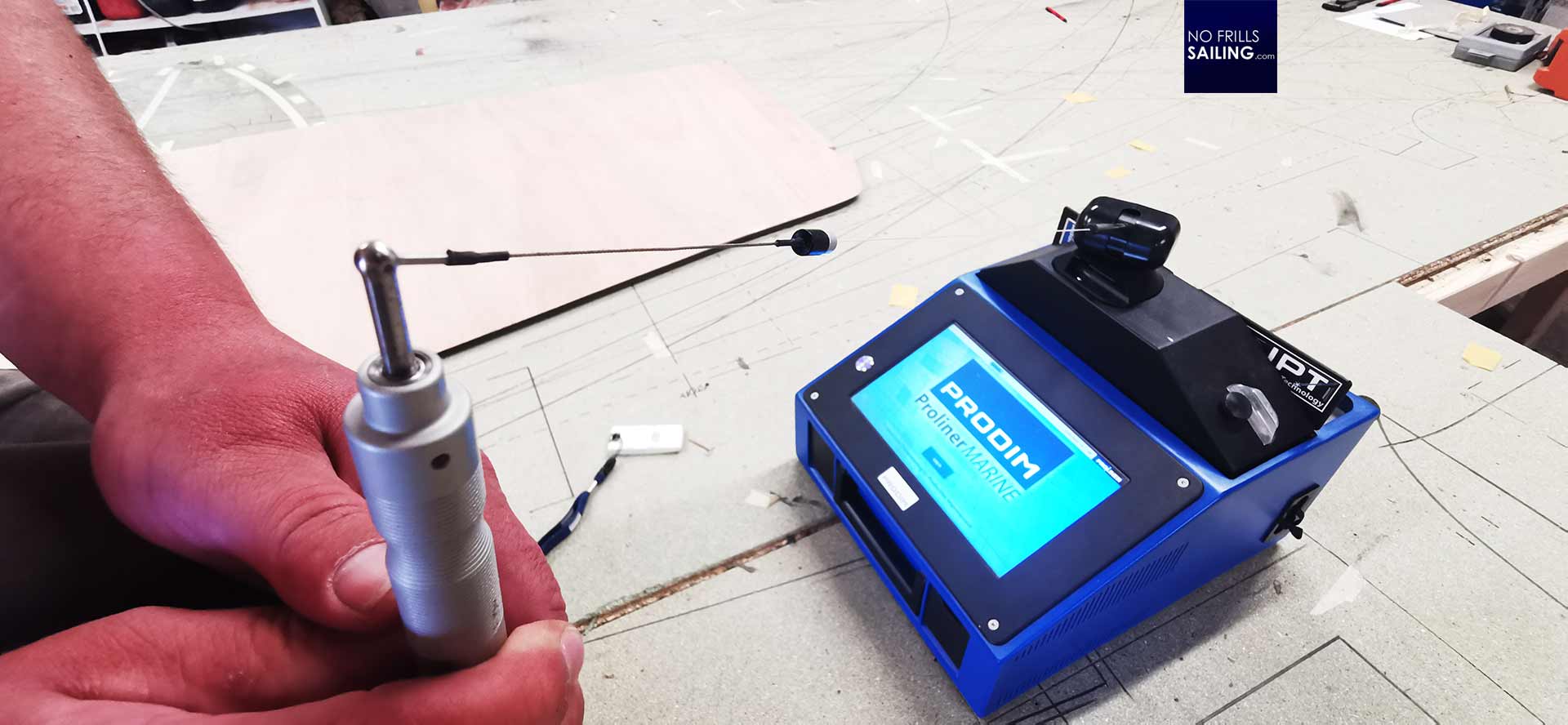
In essence, this tool consists of a “stick” that is connected to a wire. This wire is constantly under strain and connected to a coil in the mother unit. The wire itself is diverted through a 360 degree rotating part. This sensor part will measure the distance (by the amount of wire uncoiled), the direction in which the wire is pointing and the angle to which degree the stick is put down. Out of those three measurements it can assign coordinates.
Christian powers up the Proliner and opens a new folder: “Omega 42”. First thing he does is to “tell” the computer what kind of surface we have. The coordinates of my floorboards are of course a two-dimensional figure as my deck is flat, not bent. But, for example if you have a rounded flybridge or structures common powerboats, the surface can be three-dimensional too.
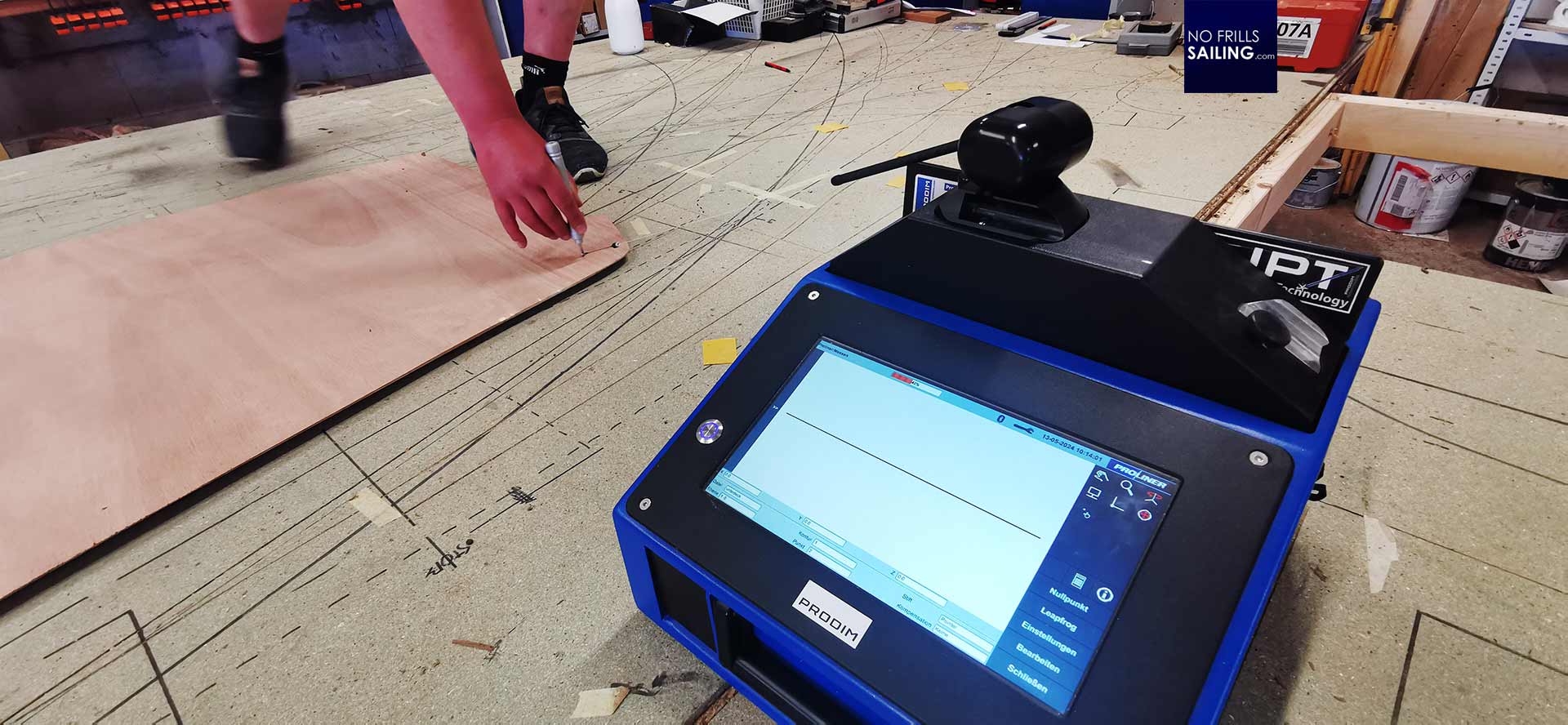
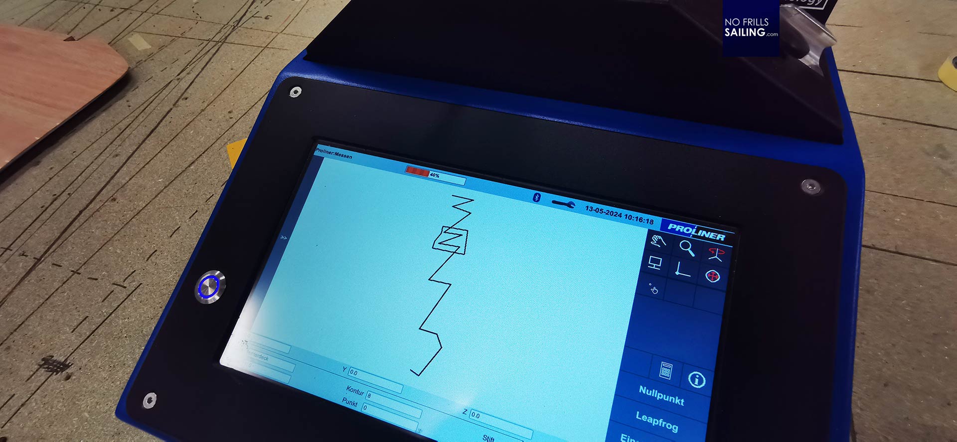
Christian puts the stick onto the deck from stern to bow. He starts to “paint” in virtual reality. Going from one end of the floorboards to the other, this painting grows to a seemingly incoherent zigzag that is going all over the raw wooden parts. The idea is that the coordinates taken now by the Proliner-computer comprise the whole workpiece. Why? Because the system needs to learn about the general or basic appearance of the part. In my case, a two-dimensional thing.
After completing this task, Cristian returns to the small screen and completes the session. The display shows a line to and fro. Logging in this line, the system now “knows” that my deck is even and to level. He looks at me and tells me that now the tricky part will begin. Tricky because what follows now is the groundwork for achieving a virtual model of the piece as accurate as possible.
Turning wood into zeroes and ones
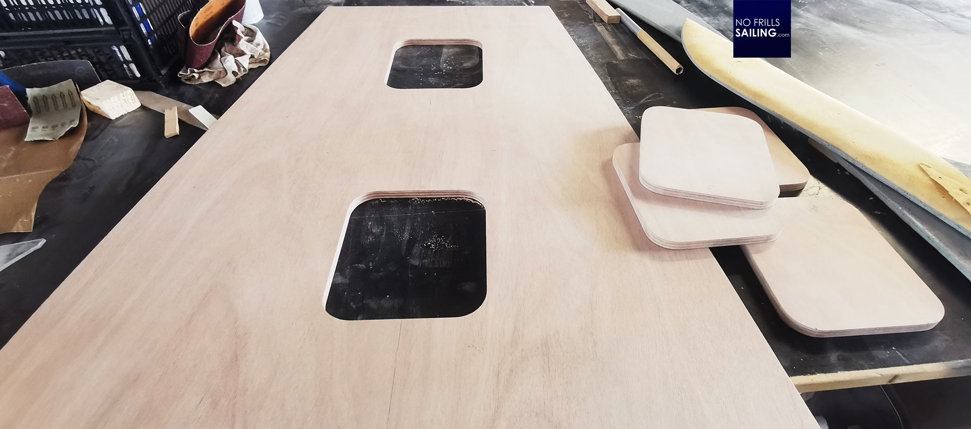
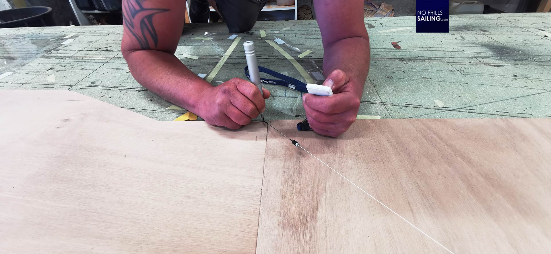
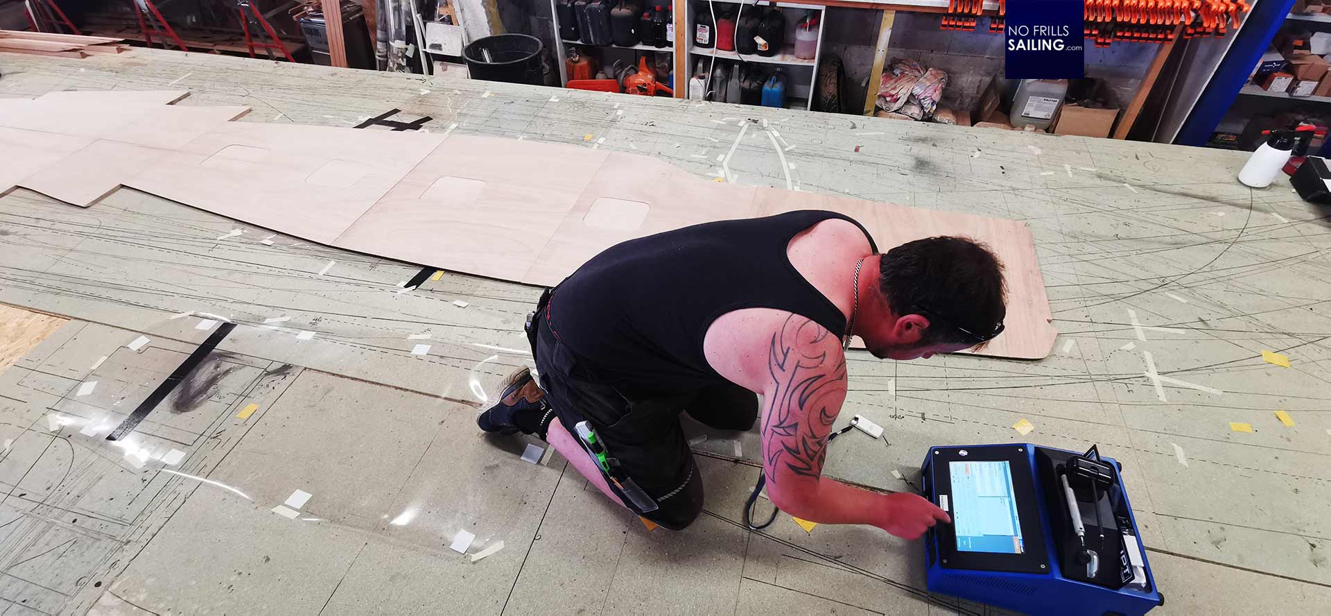
Christian kneels down, takes the “stick” in one hand and holds up a small white box that looks like a remote control of some sort. Apparently, the shapes of my floorboards aren´t easy. If you have a simple square, you just need to take four measuring points or coordinates to digitalize it. The more angles a workpiece has, the more complicated it becomes. Every corner needs a coordinate. And it even becomes much more complicated when the shapes are bent, which is the case for my deck – and is essentially apparent for any deck of any boat. In this case, the more coordinates are taken the more perfect a bent line can be reproduced.
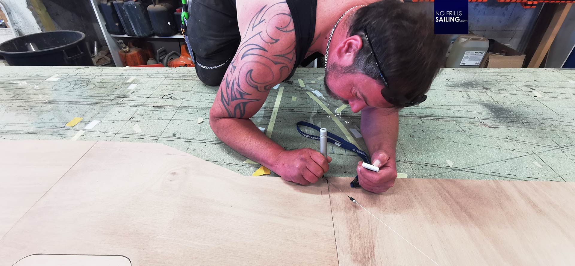
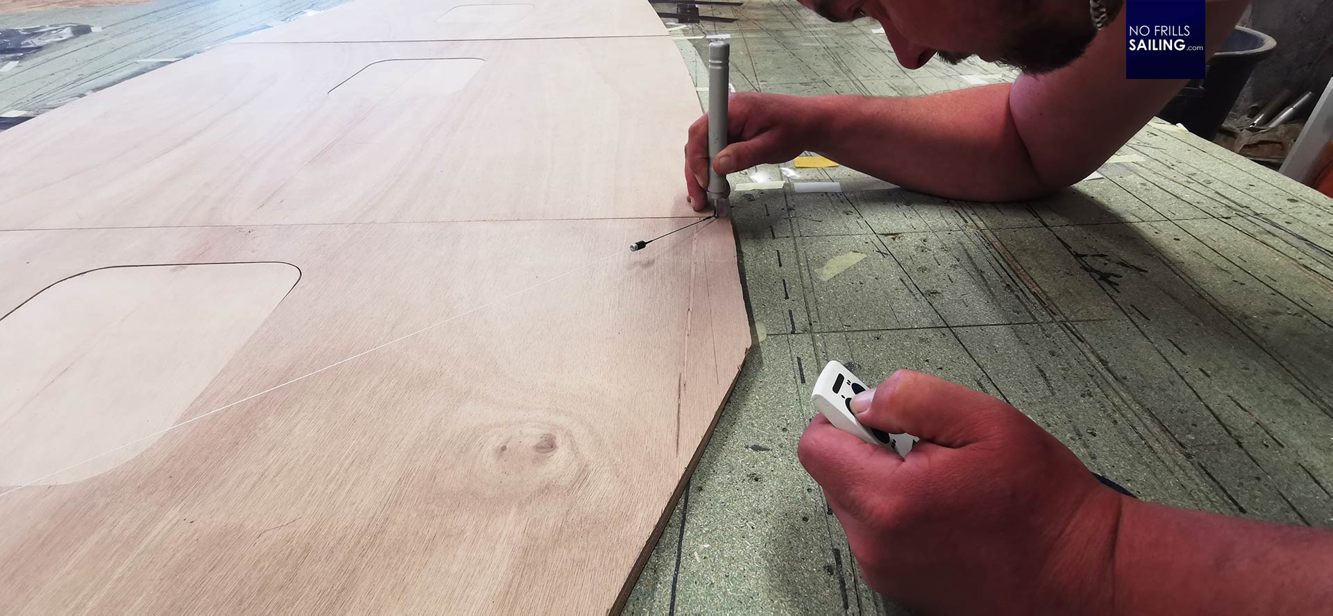
In a way, a circle is just a set of infinite individual coordinates placed around a center point. Anyway, Christian goes down to a dozen centimeters away from the floorboards and starts to put the stick to the board. Following the shape of the wooden pieces, the machine acknowledges every measurement taken by a loud “beep”. Again, the more “beeps” you get the more accurate the digital template becomes. Straight edges without any bent line in between just need two coordinates. Bent lines … well, the more, the better.
The Proliner system, as Christian explains whilst he is “beeping” his way all around the wooden piece, has an incredible accuracy. But even with this accuracy, which he says is around one to two millimeters, you will have a digital model that is just an approximation to the original. That is why he takes his time to have the stick placed as precisely as possible – and read as much coordinates into the system as he can. In the end, this is all his working time: This can be important later when customers compare offers. Somebody doing a digital template for a deck in a rush may be cheaper, but the outcome may also be sloppy.
I know start to comprehend the labor and effort that goes into a deck. We haven´t even started to produce something physical and yet several working hours will go into digital templating. I mean, this boat may be the last boat I build and therefore I want it to be as perfect as it can get. I will use the floor of my boat every time. I will look at it, there is no way to avoid this: Why should I not spent the money onto this?
First virtual floorboard
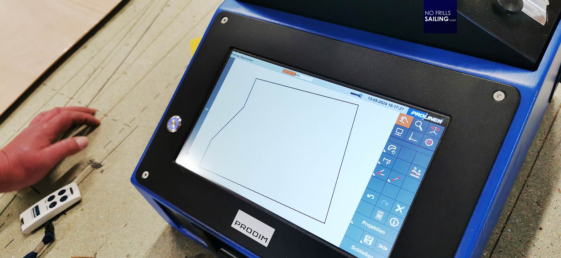
After some fifteen minutes Christian concludes taking the measurements for the first floorboard. On the screen I can see the zigzag of the “leveling” process. This is the first set of data that is deleted. What is left over is a small vector showing the floorboard´s outline. The Proliner computer is a touchscreen and being a vectorized set of data, Christian can zoom in and out at will.
Putting the wooden piece – now zeroes and ones – on maximum zoom, he shows me some inaccuracies. For example, three of the edges hadn´t been connected. One of the slightly bent lines had a “dent” because apparently one coordinate had been taken with an offset. Right here at the small screen Christian can smoothen out the small inaccuracies. The system calculates the edges. He explains that, for example, for finding the rounded edges of the four small access lids, he won´t take a set of coordinates with the “beeping”-thingy but define a centerpoint, put in a radius and the system will calculate the accurate shape.
The coordinates he had been taken for this part are just for me and this article. His colleague will start the real digitalization in a few days, but it is amazing to see how it is done and even with just a dozen quickly gained measurements the digital template looks just awesome comparing it to the real part on the working table.
I start to comprehend why his invest in this system is so clever: Working with gauge models, plastic sheets and shapes transferred with an Edding marker may work for easy shapes or small workpieces. But when a full-fledged deck is produced that runs down the whole length of a boat, you need to have accurate models. And there is another reason: The EVA-mats Christian is going produce which will be put onto the wooden floorboards are cut precisely by a CNC-machine – and this machine of course runs on 0 and 1, not on transparent plastic film with black marker.

Preview to part 2: Finetuning the digital model & production start
So, what will be the next step? After fully templating the floorboards by digital means these data are put on a stick. This stick is then fed into a computer where Christian will soften and smoothen the models, take out the inaccuracies and plan the design. I opt against having embrasures. Just as with the deck outside, I want the design to be straight and as light as possible. He promised to send me his design suggestions in the coming days.
After approval by myself, these data are fed into the CNC-machine that will then start to cut the raw EVA-plates into shape. This already works just awesome for the Teak gratings we offer to our Beneteau clients. By the way, I will surely have a real Teak grating in my Omega 42 as well as a grating in the cockpit. Anyway, this will be part 2 of this series: Digital deck design model and some iterations and how the machine cuts out the first EVA-foam floorboards. Stay tuned!
You might as well find interesting to read:
Handmade gauge model for making templates
EVA-foam floorboard fail: Buy cheap, buy twice
Interior upgrade with EVA foam